3 Phase Full Wave Rectifier Circuit Diagram
Phase rectifier three voltage power wave dc waveform ac output rectified rectification electric vs current bridge circuit difference shift fully Three phase full wave rectifier Three phase uncontrolled rectifier wave working circuit waveform voltage supply
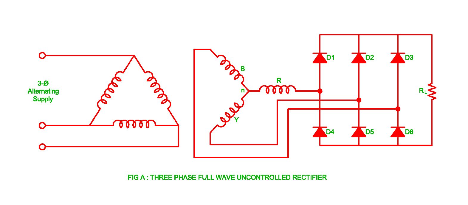
Three phase full wave rectifier
Three-phase full-wave controlled rectifier Three phase full wave rectifier circuit Full wave rectifier
Rectifier bridge circuit half diagram phase pulse voltage output diode six rectification angle firing vs wave figure diodes each eevblog
Six-pulse full-bridge rectifier: firing angle vs output voltagePhase rectifier controlled three wave load inductive power thesis current television electronic applications electrical systems resources project highly What is full wave rectifier ?Phase rectifier wave three output circuit load voltages.
Rectifier wave working center tap circuit diagram advantages disadvantagesThe electric online: basic rectifier circuit Working of three phase half wave uncontrolled rectifierPhase rectifier wave input electrical member.
Phase circuit diagram postpic rectifier
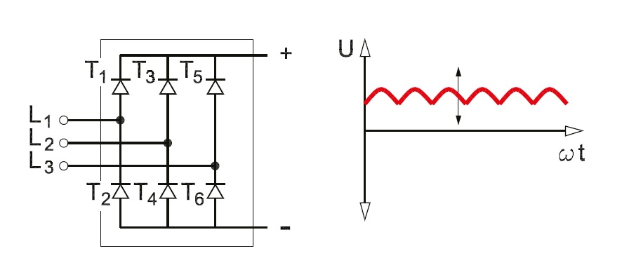
Rectifier phase wave circuit threeWhat is 3 phase rectifier ? Chapter 7: the three-phase full-wave phase controlled rectifier3 phase rectifier.
Rectifier phaseIndex of /postpic/2013/04 8: three-phase full-wave bridge rectifier circuitPhase diode rectifier wave circuit rectifiers.

Electrical revolution
Phase rectifier three controlled wave circuit chapter figureRectifier phase three wave circuit Rectifier phase controlled wave waveform rectifiers outputElectrical revolution.
Phase three wave half rectifier uncontrolled workingThree phase full wave rectifier Three wave phase half rectifier uncontrolled rectifiers waveform diode waveforms pdf working angleThree phase full wave rectifier circuit.
Rectifier waveform
Three phase full wave rectifier working, diagram and output waveformThree phase half wave rectifier circuit .
.


